
Engineering Insights
3 Phase Power Systems And How To Know That You Have Wired Them Correctly
 There are countless articles on-line describing the two varieties of 3-phase power systems and why one is more beneficial over the other based on your application. The 3-phase systems are called 3-phase delta and 3-phase wye and this document will explain how to connect your single phase heaters to such a system, and more importantly, how to check that it’s done correctly with a few simple resistance measurements.
First, you’ve got to determine the type of system you’re working with. If your electrical system has no neutral wire, you’re probably working with a 3-phase delta system where the legs of the system are connected in a triangle. Delta gets its name for the Greek upper case letter delta (Δ) which resembles a triangle. If you do have a neutral wire, you’re probably working with a wye system. Just think of the letter Y because all the lines are connected to a central node. It’s good to confirm the type of system you have by checking an ID plate or other documentation you have regarding your 3-phase system. The use of the word ‘probably’ above is used because there are exceptions to every rule. Though rare in the case of 3-phase power systems, it’s still best to check. If you have three heaters of equal resistance you’re ready to go. If you have six heaters, that’ll work too. Any multiple of 3 heaters is what you need in these types of systems.
For a 3-phase wye system with three single phase heaters, connect one lead of each heater to the central node and the other lead of each heater to one of the 3-phase nodes. If you have a multiple of 3 heaters, connect them in equal groupings in parallel. Maybe a few diagrams will help.

As you can see the 3 nodes for each leg are labeled A, B and C, which is typical. They might be labeled 1, 2 and 3. In a 3-phase Wye configuration you have the fourth node that’s labeled N or Neutral.
When checking that you’ve connected the heaters correctly you should measure the resistance between each leg (A, B and C) and the Neutral leg. They should all measure about the same, within the resistance tolerance of the heaters you’re using. You should also check the resistance from leg to leg. Check from A to B, A to C and B to C. Each resistance across those connections should be double that of a single leg, again, within the resistance tolerance of the heaters. When you take those measurements, you’re measuring the resistance of two legs connected in series, ignoring the third (unmeasured) leg. The term ‘single leg’ or ‘leg’ is used instead of a heater because there might be multiple heaters in parallel across each leg. Just make sure you know the resistance that should be present on each leg.
If R is the resistance for a single heater, and P is the number of heaters in parallel you have across each leg then the total number of heaters in your setup should be 3 x P and the resistance from each A, B or C to N should be R/P. The resistance from A to B, A to C and B to C should be 2 x R / P.
If you check your system and all the resistances are as described you can be very confident that everything is wired correctly.
When it comes to a delta configuration, the math is a little tricker and it’s easy to see why. There’s no neutral node so the resistance checks must be made between nodes A, B and C. In that case you’re measuring a single leg which is in parallel with the two other legs that are connected in series. Connect your single phase heaters as shown in the diagrams below, depending on the number of heaters you’re using.
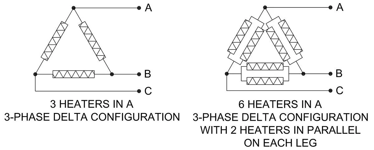
Sparing you the trouble of how to calculate the values, you should read the resistance of one leg divided by 1.5 or R / 1.5 where R is the resistance of one heater when using one heater on each leg . In other words, if you have three 50Ω heaters connected in a 3-phase delta configuration you should measure 33.3Ω from A to B, A to C and B to C.
When there is more than one heater connected in parallel on each leg of a 3-phase delta configuration, the resistance between a pair of legs is R/(1.5 x P) where R is the resistance of a single heater and P is the number of heaters in parallel on each leg.
Six 150Ω heaters in a 3-phase delta configuration where there are 2 heaters connected in parallel on each leg should give you a resistance of 50Ω from A to B, A to C and B to C.
In a crazy example of 18 heaters measuring 650Ω each, in a 3-phase delta configuration, the resistance between legs should read 650/(1.5 x 6) = 72.2Ω.
To Summarize, using R as the resistance of a single heater and P as the number of heater connected in parallel on each leg of a 3-phase circuit,
…..the resistance across any two nodes of a 3-phase wye configuration is 2 x R / P.
…..the resistance across any two nodes of a 3-phase delta configuration is R / (1.5 x P).
One additional thing to watch out for in a 3-phase wye system that must be mentioned is the voltage present across each leg. If the 3-phase system is labeled as a 480V 3-phase wye system, the voltage across each lead is only 480/√3 or 277 volts. Whatever a 3-phase wye system may be labeled (call it V), the heaters are going to be subjected V/√3 or V/1.732.
That’s not the case in a 3-phase delta system. A heater across a leg of a 480V 3-phase delta system will be subjected to 480 volts. There is no adjustment necessary with a 3-phase delta system.
This should help you to be able check your 3-phase wye or delta configuration with confidence.